Bring a material sample. Leave with a tested process.Talk with an applications advisor
FOLLOW THE MATERIAL THROUGH THE SHOP

Boss Laser application paths for real production settings

The same laser category can behave differently when material, coating, fixture, air path, artwork, inspection, and batch handling change. Use these application cards to identify the tests that matter before selecting a workcell.

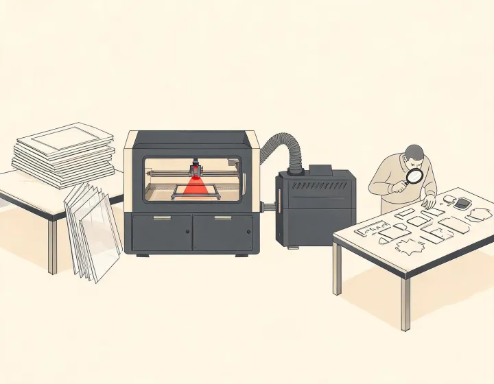
Illustrated laser workflow from material intake to inspected part
APPLICATION CARDS

Translate the use case into a test plan

SIGN & DISPLAY

Acrylic, wood, laminate, and coated media

Problem: edge appearance and dimensional fit must stay acceptable across nested parts and sheet-lot variation. Test path: record material identity and thickness, protective film condition, focus, power, speed, air assist, extraction, and cleanup. Inspect the first part and a repeated part using the same edge and dimension criteria. CO2 processing may fit many non-metal substrates, but unknown plastics can release hazardous fumes and must not be processed without material confirmation.

LIGHT FABRICATION

Metal cutting and part identification

Problem: a shop may need both geometry and traceability, but those jobs can require different source, power, optics, gas, and fixturing choices. Test path: separate cutting thickness and edge criteria from marking contrast and code readability. Check reflective behavior, assist-gas requirements, heat effects, extraction, and downstream finishing. Fiber capability is not a blanket promise for every alloy or thickness; validate the exact grade and configuration.

PERSONALIZATION

Variable artwork on repeat fixtures

Problem: artwork changes while the mark or engraving must land consistently. Test path: define file preparation, artwork origin, lens field, fixture datums, focal height, and the acceptable placement window. Run a first-piece check and a mid-batch check, then preserve the fixture version with the saved job record. Surface finish, coating, and color can change contrast even when geometry is unchanged.

EDUCATION & MAKER LABS

Shared access with teachable controls

Problem: many users bring unfamiliar materials and varying skill levels. Test path: build an approved-material list, supervised file review, enclosure and interlock checks, exhaust verification, start-up and shutdown routines, and a visible stop-work rule. Throughput must include instruction and cleanup time. A settings chart is a starting reference, never permission to process an unidentified material.
SELECTION CHECKLIST

CO2 or fiber? Begin with five observable facts

Source labels are useful only after the application is defined. Fill the worksheet with a representative sample in hand, then compare the quoted configuration against the complete workcell.

  1. Material: exact substrate, alloy, coating, and thickness.
  2. Result: cut, engraving, permanent mark, contrast, edge, or tolerance.
  3. Scale: usable part area, batch quantity, and changeover frequency.
  4. Environment: extraction, cooling, electrical supply, access, and fire controls.
  5. Verification: inspection method, repeated run, and owner of the saved settings.

Method trade-offs to document

Higher power may increase process headroom, but it does not remove the need for a stable optical path, suitable gas or air assist, extraction, and motion control. A larger bed accepts larger stock, yet it also changes floor space, loading reach, duct routing, and material handling. Faster demonstration settings can reduce cycle time while narrowing the process window or increasing edge cleanup. Compare total workflow evidence—not isolated headline values.

TEST THE EXCEPTION, NOT THE EASY SAMPLE

Choose the material that exposes your risk

Bring the thickest stock, smallest detail, hardest fixture, or most sensitive finish you expect to run. Define the acceptable result before the demo and repeat the chosen condition. That creates a useful basis for machine, accessory, extraction, and training decisions.